
Heritage Aluminium Hopper Heads for Period Homes
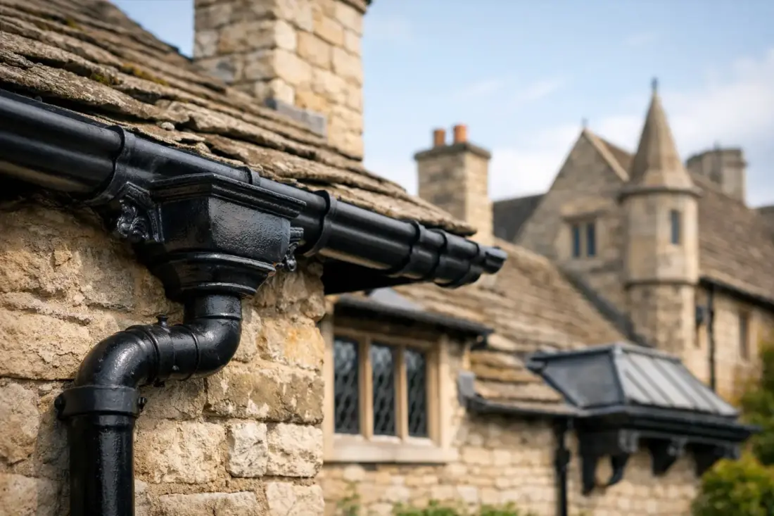
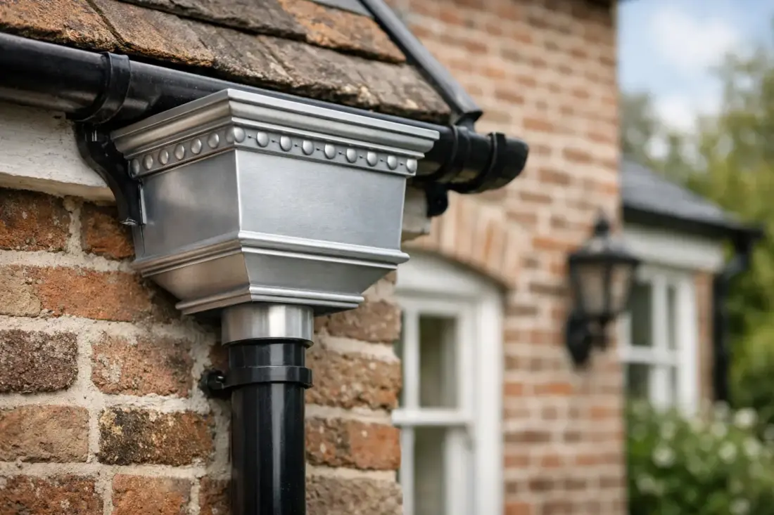
A hopper head is a small component with a very visible job. Positioned between gutter outlet and downpipe, it collects roof water at a key transfer point while adding the detail that gives a traditional rainwater system its character. For period properties, heritage aluminium hopper heads provide the familiar depth, shape and decorative presence of cast iron, without the weight, corrosion concerns or ongoing repainting associated with older materials.
They are particularly well suited to Victorian, Georgian and Edwardian homes, conversion projects and buildings where plain plastic fittings would look out of place. The right hopper head should not be chosen on appearance alone, however. It must match the gutter profile, downpipe size and roof area so the whole system carries water away efficiently.
Why hopper heads matter on traditional buildings
Traditional hopper heads were often made from cast iron and fixed at prominent points on a façade, commonly below a gutter outlet, at a valley junction or where several gutter runs meet. Their purpose was practical: they slowed and directed water into the downpipe, giving a visual indication if a blockage or overflow was developing.
That function still matters. A properly sized hopper head provides a useful collection point where water leaves the gutter. On roofs with valleys, dormers, parapets or large catchment areas, the volume arriving at one outlet can be substantial during heavy rainfall. A decorative head that is too small can become the restriction in an otherwise capable system.
Aluminium makes sense where traditional appearance and long-term performance need to sit together. It is lightweight, corrosion resistant and does not rust in the way untreated cast iron can. This makes handling easier during installation, particularly at height, while reducing the maintenance burden for homeowners and facilities teams.
Choosing heritage aluminium hopper heads by profile
The best starting point is the rainwater system already specified or installed. A hopper head should look like part of the same family as the gutter and downpipe, rather than an added fitting selected in isolation.
For classic domestic elevations, a square, rectangular or decorative cast-style hopper head can sit well with half-round, ogee or moulded gutter profiles. More formal buildings may suit a deeper, more ornamental pattern, particularly where original rainwater goods have distinctive details worth retaining. On a simpler cottage or terrace, a clean traditional square design may be the better choice.
Downpipe compatibility is equally important. Hopper outlets are made to suit particular downpipe sections, commonly round or rectangular. The outlet needs to connect securely to the pipe below, using the correct socket, swaged section or adaptor where required. Trying to force mismatched components together can create poor alignment, leaks and an untidy finish.
Where a building has existing cast iron guttering, measure rather than guess. Record the gutter profile, outlet position, downpipe dimensions and available fixing space. Older properties often contain non-standard arrangements, and a replacement may need to work around masonry details, render, brackets or previous repairs.
Decorative detail should suit the elevation
A heritage hopper head does not need to be highly ornate to look correct. The most successful choices usually reflect the scale of the property. Large, elaborate heads can suit a substantial frontage, church hall or public building, but may overpower a modest bay window or rear extension.
Look at the existing clues: original downpipe clips, air bricks, window surrounds, door furniture and neighbouring properties built as part of the same terrace. These can help establish whether the building calls for a restrained Victorian-style detail or a more decorative pattern. For listed buildings and homes in conservation areas, photographs of the original system can also be valuable when discussing the replacement approach with the local authority or project architect.
Capacity is as important as appearance
Rainwater goods work as a system. The gutter captures water, the outlet transfers it, the hopper head receives it and the downpipe discharges it. Restricting any part of that route can cause overflow during intense rain.
A small roof area with a straightforward pitch may only require a standard domestic arrangement. A large slate roof, valley intersection or concealed box gutter can need greater capacity, larger outlets or more than one downpipe. This is where a contractor, architect or specialist supplier should assess the roof plan rather than selecting by visual preference alone.
Pay particular attention to valley outlets. Water from two roof slopes can arrive quickly at the same point, bringing leaves, moss and debris with it. A suitably generous hopper head offers a more forgiving entry into the downpipe, but it is not a substitute for correct gutter falls, sufficient outlets and routine maintenance.
If the property is exposed to wind-driven rain or sits beneath overhanging trees, allow for the real conditions on site. A design that performs on a sheltered elevation may need more capacity and more frequent cleaning on a rural property or heavily wooded plot.
Finishes that work with heritage architecture
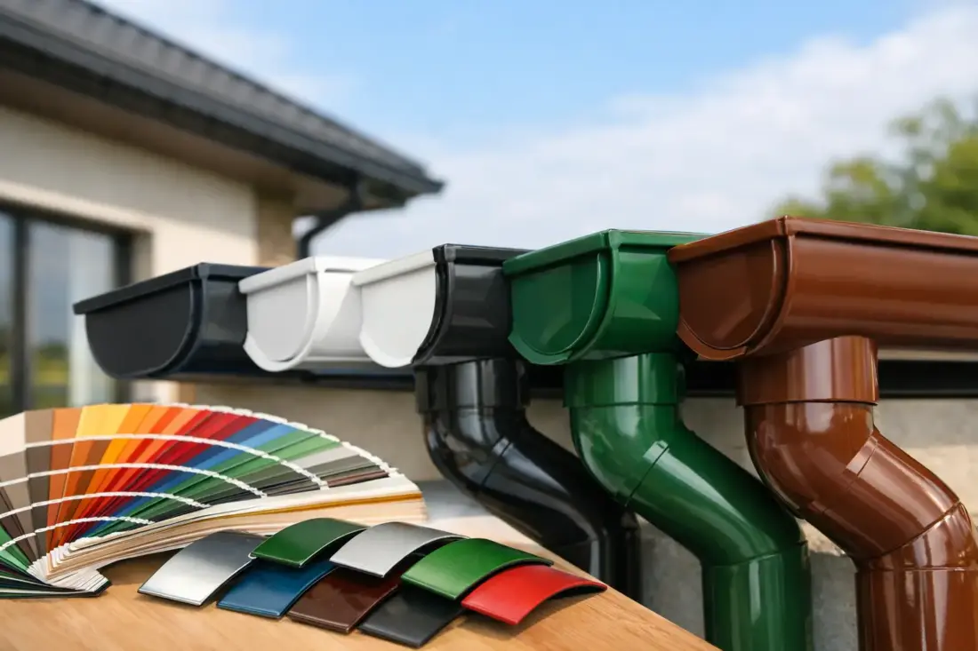
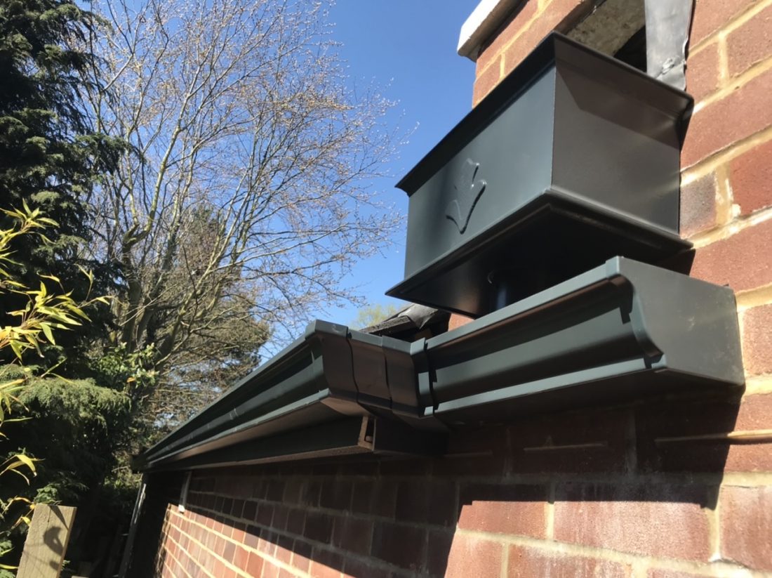
Black remains the familiar choice for traditional rainwater systems, and it gives aluminium the visual character of painted cast iron. It is not the only option. Powder-coated aluminium can be specified in a wide range of colours, allowing the hopper head, gutters and downpipes to coordinate with window frames, fascias, cladding or brickwork.
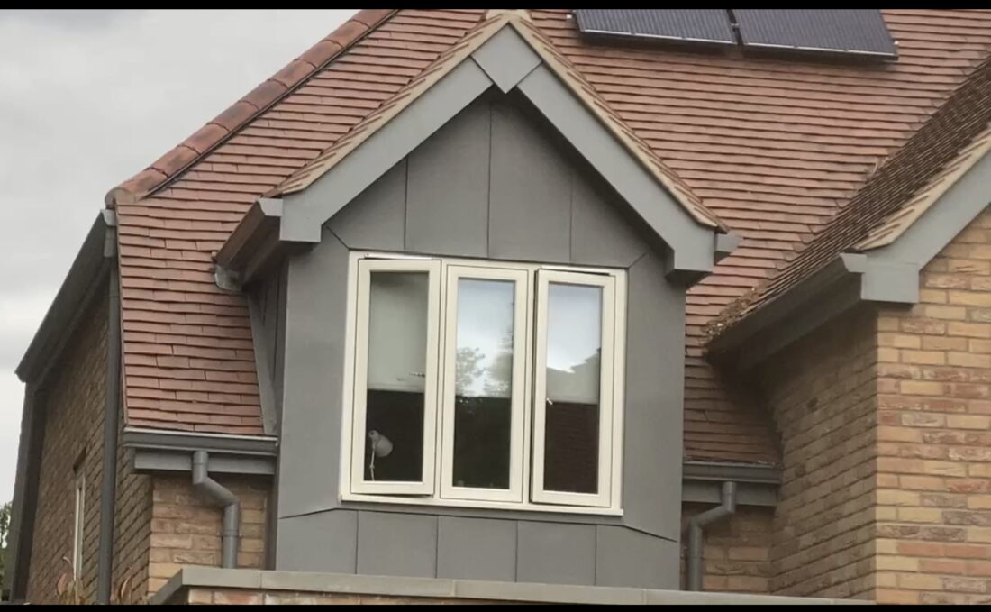
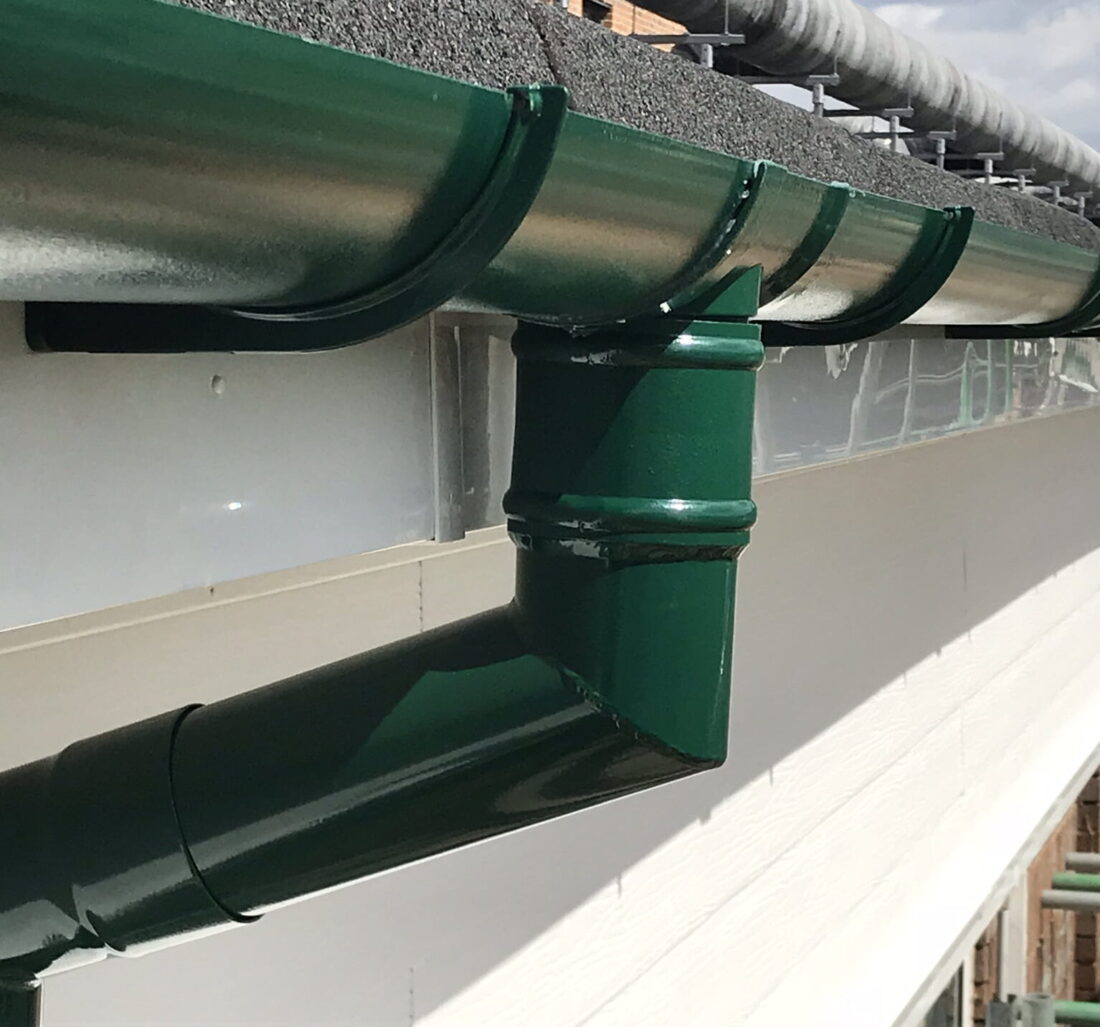
For a period property, the aim is generally a finish that supports the architecture rather than competing with it. Deep black, heritage green, dark grey and selected bronze tones can all work well depending on the building. A contemporary extension may use the same traditional hopper profile in a colour matched to aluminium windows, helping old and new sections feel considered rather than disconnected.
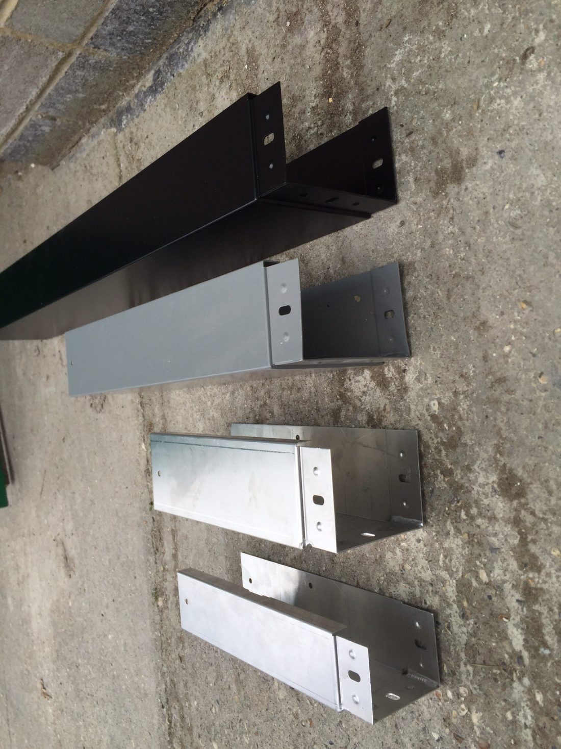
The coating should be selected across the full rainwater package. Ordering gutters in one shade and fittings in another can leave noticeable variation, especially on a front elevation. Confirm the required colour, sheen and system components before manufacture or powder coating begins, particularly where bespoke lengths or non-standard items are involved.
Installation details that protect the finish
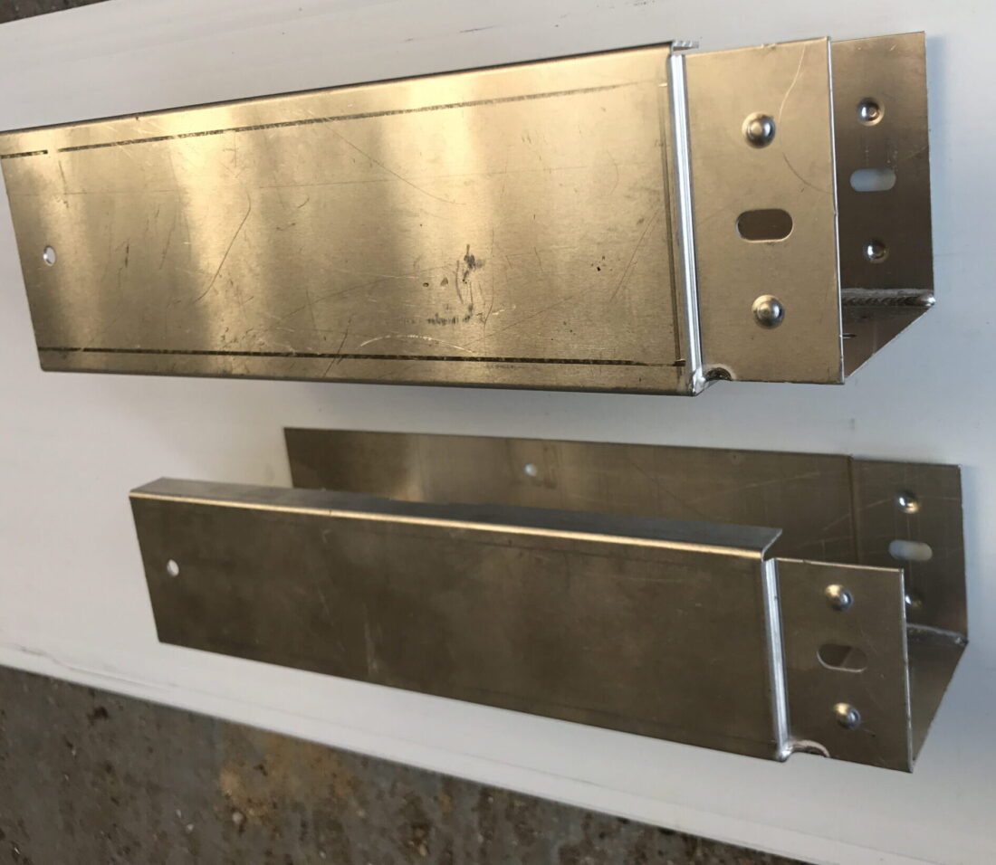
Aluminium hopper heads are lighter than cast iron equivalents, but they still need secure fixing into sound substrate. Fixings should suit the wall construction, whether brick, stone, render over blockwork or timber-framed cladding. On old masonry, avoid relying on weak mortar joints or damaged brick faces.
The vertical line matters. Set the hopper head directly above the downpipe so water enters the outlet cleanly and the finished run looks intentional. Brackets should support the pipe at appropriate intervals, with joints and offsets arranged to avoid strain on the hopper outlet.
When cutting or adjusting associated aluminium components, use suitable tools and protect exposed edges as required by the system specification. Care during handling also protects the powder-coated surface. Dragging components across scaffolding boards, stacking them without separation or overtightening fixings can mark a finish that should otherwise last for many years.
For supply-only work, accurate measurements and a clear component schedule help avoid delays. For more involved refurbishments, a cut-and-drop service can reduce site cutting, while professional installation is worth considering where access is difficult, the roof layout is complex or the property has heritage constraints. Gutters Direct can assist with selecting compatible aluminium profiles, downpipes and fittings for a complete arrangement.
Maintenance remains part of good drainage
Aluminium reduces the risk of corrosion, but no rainwater system is maintenance-free. Clear leaves and debris from gutters, valley outlets and hopper heads regularly, especially after autumn leaf fall and storms. Check for standing water in the gutter, staining beneath outlets, loose clips and water escaping over the front of the hopper head.
If overflow occurs, do not assume the hopper head is undersized. The cause may be a blocked downpipe, inadequate gutter fall, a partially obstructed outlet or debris trapped at a bend. Resolve the underlying issue before replacing components.
A well-chosen heritage hopper head does more than complete the look of a period elevation. Matched properly to the gutter, downpipe, roof capacity and finish, it becomes a durable working detail that keeps rainwater moving where it should – away from the building fabric.